Magnetic Engines has a comprehensive list of engine repair capabilities for various kind of hospital repairs and modules replacements on the CFM56 engine type. Highly professional engine team can perform the repairs and service the engines in our engine shop in Tallinn or at the customer facility. Every engine managed by Magnetic Engines team is treated with special care, professionalism and expertise.
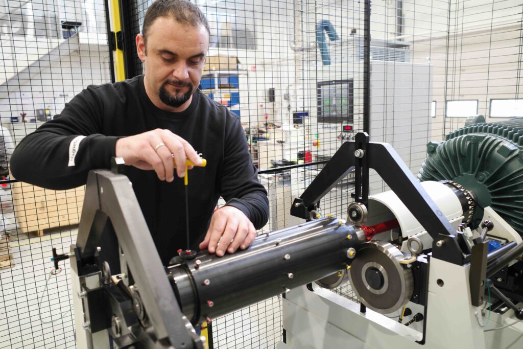
Slobodan Marinkovic, Engine Workshop manager, invites us to take a closer look at one of the procedures we are performing for our customer and gives experts insight in this step-by-step guide to OGV (Outlet Guide Vanes) replacement on CFM56-5B engines. A very similar procedure is performed when engine shop module 21 (Fan and booster) requires replacement due to LLP expiration.
Like any other engine maintenance work, OGV replacement involves a set of strict rules related to tooling and procedural steps determined by the manufacturer which ought to be carefully followed. The team takes special care when dealing with tooling and engine parts to avoid damage to these expensive materials during removal and installation.
To start the engine disassembly, the engine is towed into the designated workshop area and carefully placed onto the engine pedestals. Then, a series of steps are taken to gain access to the OGV itself and complete the replacement procedure. Read on to find out.
Step 1 – Front & rear spinner cones removal
Front and rear spinner cones have twofold roles in the aircraft engine. Firstly, they secure the airflow at an appropriate angle. Secondly, they help to avoid any potential FODs (Foreign Object Debris), protecting the primary airflow and preventing the engine from being damaged mid-flight. The engine technicians use mechanical tools to remove the front and rear spinner cones, gaining access to engine fan blades.
Step 2 – Fan blades removal
Fan blades produce 80-85% of the engine thrust. They are one of the most loaded parts of the engines, made of titanium, designed in 3D shape. There are in total 36 fan blades on the CFM56-5B engine. Interestingly, titanium is used for manufacturing of fan blades because of its strength, durability and low-corrosion properties.
Step 3 – Splitter fairing removal
This engine part serves to separate the airflow into Primary and Secondary. The splitter fairing is connected to the OGV shroud support with a number of bolts, and in order to remove it, special tooling is required.
Step 4 – Booster module removal
In this stage, firstly, fan disk and fan shaft are disconnected. Then booster vane removed from fan frame. A crane supports the booster module, and the booster removal fixture is placed onto the fan disk to proceed with removal (Picture 1 & 2). For this process, dozens of specially designated tools are used. When the booster module is finally removed, it leaves 1 & 2 bearing support exposed as shown in Picture 3.
Step 5 – OGV removal
OGV (Outlet Guide Vanes) serves to stabilize the airflow in the engine. In this stage, the bolts which are holding OGV to the fan case are removed. There are a number of vanes, and the engine technicians put extra care in removing each one of them, to avoid damages.
Step 6 – OGV inner shroud support removal
As its name suggests, the inner shroud serves to support the vanes. In this step, bolts are removed, and no special tooling is required for the process. When the inner shroud support is removed, it leaves 1 & 2 bearing support wholly exposed, and the engine technicians can proceed to the central part of the procedure – replacing the old inner shroud support with a new one
Step 7 – OGV inner shroud support installation
This is the step where the old snner shroud support is being replaced with a new one. The engine team continues with the installation of all engine parts mentioned earlier, following the procedural steps, guides and rules set by the manufacturer.
Step 8 – OGV installation
Once the inner shroud is installed, it is time to proceed with vanes installation. Each vane is manually installed, with special care.
Step 9 – Booster module installation
In this stage, the engine technicians pay special attention to the correct and precise positioning of each part, according to the top vert. Fan shaft and fan booster vane need to be heated to specific temperatures to ensure their diameters are increased enough for easier booster module installation. Next, the fan bolts need to be tightened with special torque wrenches, under strict manufacturing procedure. And finally, booster vane needs to be installed on the fan frame.
Step 10 – Splitter fairing installation
Then, the splitter fairing is installed. In some cases, it also needs to be preheated to certain degrees to be positioned over inner shroud easily and precisely.
Step 11 – Fan blades installation
During this stage, there is a special procedure which requires lubrication of the dovetail and mid span shroud in special ointment or spray. Dovetail represents the root of the fan blades, and spraying it helps to reduce fan disk depletion. Once this is done, the spacers which secure fan blades are positioned, and then the fan blades are installed one by one.
Step 12 – Front & rear spinner cone installation
The final step of the procedure is to install front & rear spinner cones back. Preheated is needed for the rear spinner. Once this is done, the engine is ready!
AND THE ENGINE IS READY!
 go back